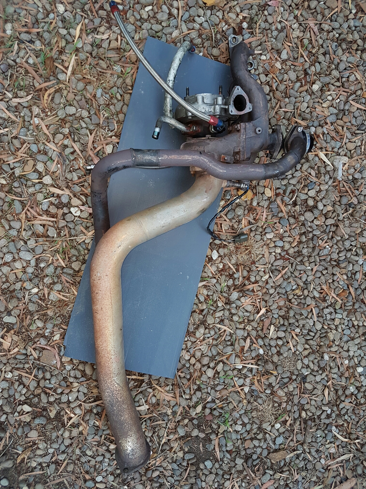
More progress, although mainly fiddly, small tasks. I started the day by removing the old studs from the exhaust manifold. They came out smoothly and were in good condition. The new turbo came with new studs and nuts so they will be kept for spares.

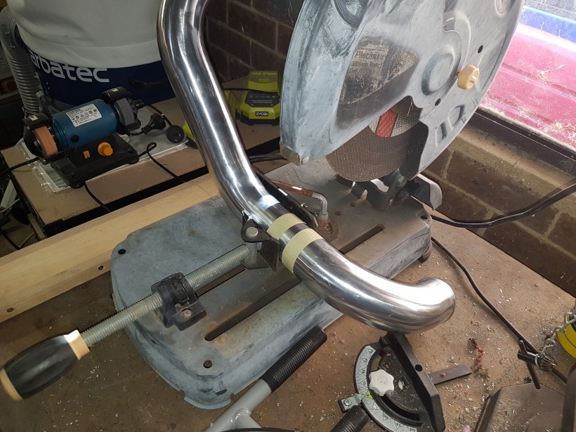
The new studs are quite long and have a square section on top which I used small vice grips to tighten. I used loctite, even though I’m not sure it won’t just burn away but it was worth trying. The picture below shows the long studs fouling in various places so I cut and filed them shorter.


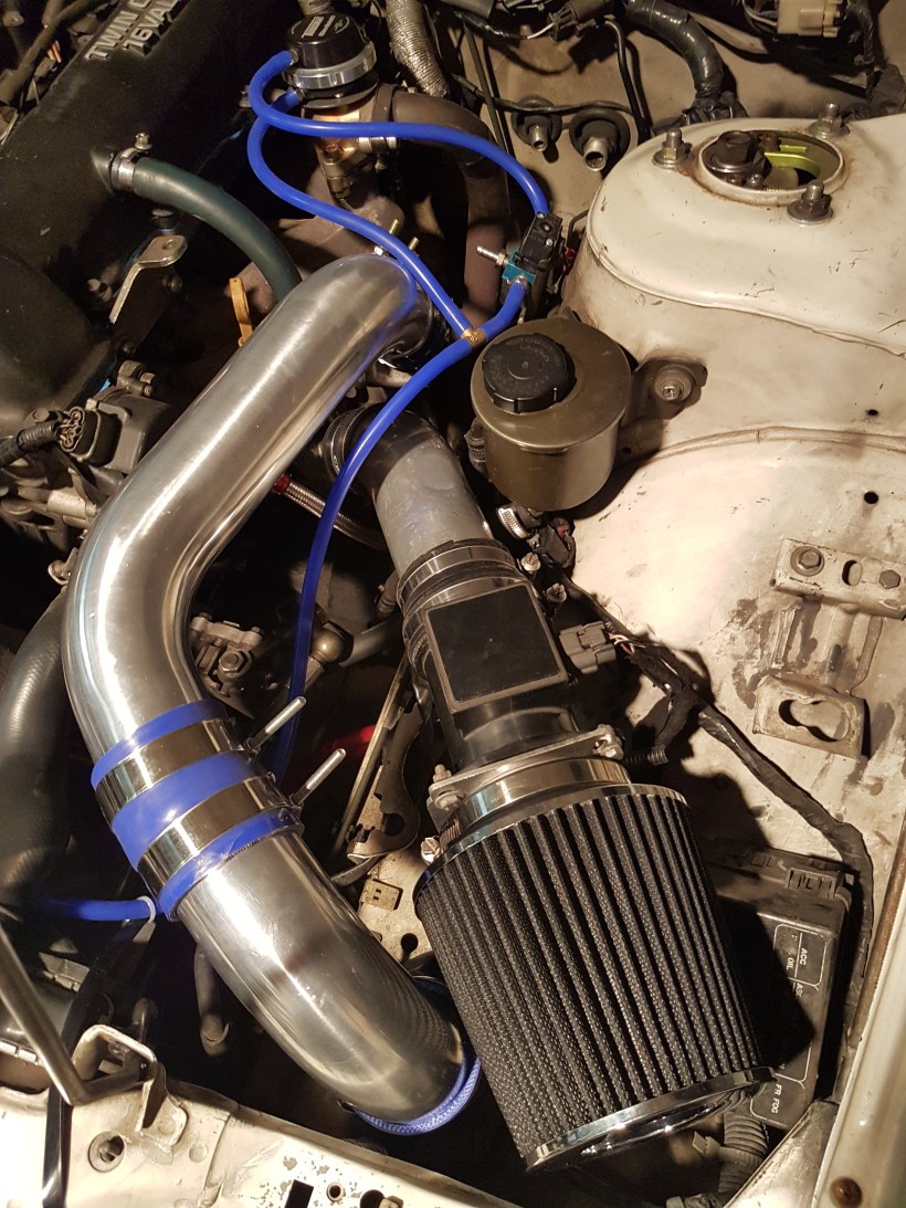
I came across the first problem in the process so far, in that the actuator fouls the intake snorkel.


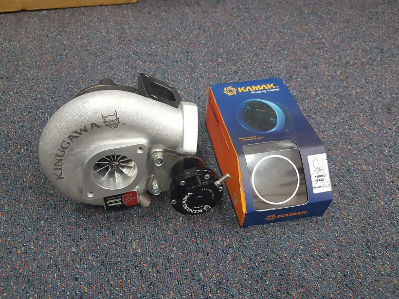
Fortunately I’m using an external wastegate so the actuator can be ditched. The kit came with an extender for the inlet snorkel but the supplied studs aren’t long enough to fit. Using this with longer bolts (supplied from elsewhere) would be a simple work around for those using the internal wastegate.


Next up I tested fitted the braided water lines and dummy fitted the whole assembly in place. Everything looks like it will sit perfectly so very happy with the job so far.

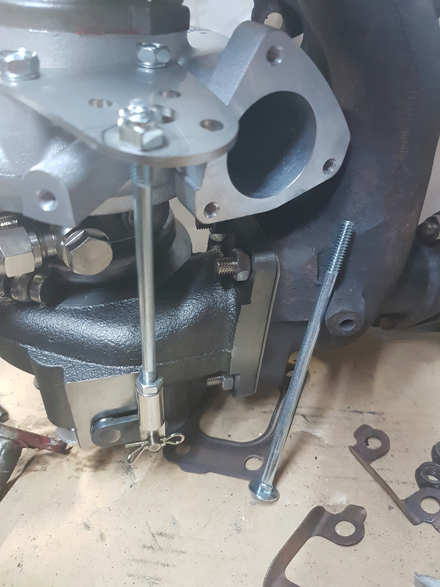
Finally, I disassembled the actuator and replaced it with a modified bolt. This was tricky because the thread on each end of the original actuator rod is a different pitch. I cut the top off a 1/4 inch bolt (pictured), cut the M6 x 0.75mm thread in its place and then bolted up. The result is a secure, mechanical locking of the internal wastegate flap shut. It is also completely reversible.

Progress now will be stalled until the mild steel flanges arrive in the mail so I can re-plumb the wastegate pipe with the new connection. Very happy so far with how things are going.

Progress! As of this evening, the turbo, manifold and dump are off the car. Everything went quite well, the only drama was having to cut the dump pipe wastegate section to allow the whole assembly to come out in one piece. Some of the nuts weren’t that tight so this may be a timely intervention.

The plan is to have the external wastegate pipe feed back into the main dump where it is visually lined up in the above photo. It currently hugs the gearbox and joins back to the dump towards the rear at a right angle. A set of flanges will be added near the new junction so the entire wastegate pipe can be unbolted to free up room in the engine bay when needed. Improved convenience and flow.

What will be tricky is finding a good place for the bung to be welded on for the wide band O2 sensor. Space is tight in that part of the engine bay.

I did find that there was a significant gap on one side on the manifold to external wastegate junction, with one nut coming loose and falling off somewhere. Some response and power would have been lost from this so it is encouraging to think of the improvement that will be made.


The new turbo is bigger than the old, but not as different in size as the HKS 2510 was compared to the T25G as shown on the turbo upgrade/change page.

I have test fitted the dump pipe and manifold and everything lines up perfectly. The kit came with new studs and nuts, so putting it all back together should be pretty easy. The turbo oil drain from the old turbo might be needed but that is not a concern.

I took off the rocker cover and the VTC assembly has been removed. It should be sitting in the large gap in front of the left cam. This means it was probably rattling and the owner removed it instead of repairing. If my understanding is correct, this means the low/mid range is compromised by the fixed timing, which accounts for my impression of lag since owning the car. The effect on power is shown in the graph below, my engine is stuck on the ‘I’ curve. Depending on the difficulty I could buy a new VTC mechanism and refit it. I could also put in an adjustable timing gear to find a better compromise, but that won’t be happening in the short term.

vtc

Not sure of the time I’ll have tomorrow but I may start hacking up the dump pipe or reassembling the new turbo.

The next phase of the build has (kind of) begun. My previous plan was to take the dump pipe/turbo/manifold  assembly off the car and to an exhaust shop for some modifications. I then thought I might as well have a go myself. I already have a nice little portable stick welder, which has the power, but not the accuracy for the job. Fortunately, it is upgrade-able to a TIG welder by adding a torch and some argon gas.

Buying these parts was a bit of an ordeal. I tracked down the parts at a local tool shop and went in with item numbers from their website. The person assisting me had no idea what was going on, and when I got home I realised he had given me an LPG regulator which didn’t fit the argon bottle or torch. Furthermore, the torch was missing the collect holder, a crucial part that screws into the torch body and then everything else into it.

Even getting the argon bottle was frustrating. A few years ago, welding with gas at home meant entering a contract and paying bottle rental on top of the gas costs. Bunnings and other places now have $99 size D bottles of gas available at their stores. The catch that isn’t priced on their website is the $200 bottle deposit. Future refills will be $99 and if I’ve ever had enough, I can return the bottle for my $200 back.

The next day I headed back down to exchange the regulator and get the missing part of the torch. When the assistant opened up another box of the same part, it was missing everything except the torch shell and hose! Apparently people help themselves to things at “the back of the store”. He made up the parts with the packet from a third box, and was very helpful and apologetic.

A quick test weld on some scrap revealed the process is so much easier, neater and more accurate than stick welding. I’m very confident of getting a good result on the exhaust. Mild steel flanges and new gaskets have been ordered to make up the new join I will be adding in to the wastegate pipe.

Other than that, a new rocker cover gasket is on the way, so I can open up the top and see what cams and gears are installed. While I’m at it, I’ll install the rocker arm stoppers.

One week until I’m on an extended Christmas break so many updates to come.

20161117_160307.jpg

Yesterday the Sileighty went on the dyno at Unigroup as planned. I was pleasantly surprised to find that Yavuz himself ran the car. His polish really comes through in the patient and calculated way he approaches the car and the feedback he gives. The fact that he starts the session by asking about the aim and where the car is heading makes so much sense.

Last time the car made 170 rwkw, started to heat soak and ping. I left with instructions not to push it. Since then I had changed to 2 inch muffler to 3.5 inch, all new intercooler and piping, base timing corrected (5 degrees of advancement), shortened intake pipe and dump pipe pin holes welded.

20161118_062518.jpg

This time the car made 181 rwkw with less timing and more fuel key places (for safety). The boost was upped a tad bit to around 18 psi. I upped the aggression of the response in the boost controller n the way home which further improved the mid range. The net result is a safer level of tune with more power. The dip in the midrange is a misfire that developed on the last run. I haven’t changed the spark plugs yet, so when I do, I’ll gap them smaller and get a colder heat range to match the higher boost.

Discussions with Yavuz were probably the most interesting part. He played with settings in the ECU and performed runs to check and verify the changes. The most interesting one was moving the VTC cut off above the rev limiter. This should have the effect of killing power above 5750 rpm as the cam timing chokes the engine. It made no difference at all which Yavuz suggests the engine might have cams and a replacement adjustable cam timing gear. The solenoid still clicks so either this or something broken up top.

The car has a clean bill of health so now I can safely advance to the next step and start pulling bits off for upgrades.


After an insanely busy period at work the light is at the end of the tunnel. Most of the bits are available to fit the new turbo and have the car tuned. I have ordered and am waiting on a wide band 02 sensor that is compatible with Nistune. It also has an analogue out signal for use on the display screen that I will soon have time to work on.

I have planned out a course of action for the entire process:

  • Dyno the car to check if everything is OK after changing the rear of the exhaust, the intercooler and piping and fixing the base timing.
  • Remove the old turbo, manifold and dump pipe, dump oil and water in the process.
  • Take the assembly to an exhaust shop to weld in the bung for the wide band 02 sensor and modify the wastegate pipe to merge more smoothly. I would also like a flange welded on so I can remove this part to make dump bolts much easier to access.
  • Fit oil cooler and winged sump.
  • Fit sensors for oil pressure and various temperature probes.
  • Change fuel filter and fit solid steering spacer, perhaps some other small bits.
  • Fit new turbo with supplied braided lines, new gaskets, etc.
  • Wire up Z32 AFM plug in parallel for changing instantly when tuning.
  • Drive car to be tuned.

The new setup will initially have both an internal and external wastegate. Both setups have a 15 psi spring that feels quite rigid. If no boost source is connected I trust they will still seal in the exhaust flow. Therefore I should be able to complete back to back testing of the wastegates by simply plumbing boost lines to one or the other.

Having the wide band 02 sensor and Nistune means I can touch up the tune on the road. The software will trace the intended air fuel ratio in the tables and log the output of the 02 sensor. I can simply trace and tweak as needed.

A lot of work ahead but a lot of time and energy to do it. Dyno run is booked for Thursday so it all starts soon.

Work is very busy but some progress has taken place on the car. On the weekend, I shortened the intake pipe from the turbo to the air flow meter. It was previously too long, with the pipe sticking through the opening of the afm and jamming the pod filter into the corner of the engine bay. Like the intercooler piping, a metal drop saw was used to shorten the pipe before being deburred and thoroughly cleaned. A new pod filter was purchased for $30 and the afm was cleaned with dedicated cleaner spray for good measure. The end result:

20161023_152826.jpg

How does it drive? Exactly the same, but once again, I have peace of mind knowing that the setup is tidied.

The new turbo arrived on Monday, and looks the goods. The kit came with gaskets, braided lines and even a free boost gauge. I will fit the new gauge because my old one doesn’t illuminate at night.

wp-1477527294077.jpg

The internal wastegate is tiny but seems to seat really well on the exhaust housing. I definitely don’t want to weld the flap closed, so I’m confident little to no modification will be necessary to keep using the current external wastegate. The minimum will be simply having no boost line to the actuator, which will leave the spring inside to hold the flap shut. If that proves unreliable, I can put something solid inside to replace the spring.

The final thing I’ve been working on is some of the rougher aspects of the tune. The idle was always super dodgy, but only from  certain point. Initial start is fine, then it went rough, later correcting as more temp was gained. As Nistune is connected to the running engine, it highlights which tables are being accessed to calculate fuel and timing. With some trial and error, I manage to track down the issue to having too advanced timing in the 30-50 degrees C coolant temp.range. I removed timing in real time and the effect on the idle was instant. Burn changes to ECU and fixed!

I have also been going for short drives and logging them in Nistune. Unigroup logged a dyno run for me last time round, so I now have some good data. At high loads, the RB25 afm is close to maxed out, reading 4.9 volts of a possible 5.1. The new turbo will likely cause trouble immediately when attempting to tune with its increased appetite for air. The injectors are only at 60% duty cycle, so I think they will be fine to retain. As a rudimentary calculation, 60% is supporting 170 rwkw, so 100% should support 283 rwkw.

The following is a screenshot from the Nistune software. The fuel and ignition tables are seen on the left, with the log player on the right. The maps are highlighted to show where they are being read from, and actual timing values and other details can be seen in the top right:

nistune-screen

The result of all of this analysis is the purchase of a Z32 afm from Just Jap. I read a lot of talk on forums about ‘fakes’ that look like genuine units but deliver a poor output signal that maxes out far below where it should. $323 delivered with a plug compared to an eBay copy for $100 is frustrating, but sometimes you have to pay the premium to ensure you get the right product.

I previously mentioned that I filmed my night at WSID with a Samsung Gear 360 camera. The result of that has been online for some time, but I had forgotten to post it here. On a phone or tablet, move the device around to look around the car. On a laptop computer, use the arrows in the upper left or the drag the mouse to change the viewpoint. Enjoy:

I’m a bit slow to report but the intercooler went on without any fuss. The offending pipe was cut down, deburred and cleaned out. It’s vital to remove any metal dust and fragments very carefully before putting everything back together.

wp-1476654749339.jpg

Everything now sits nicely under the bonnet. The trickiest parts were getting the little rubber hoses onto the cold pipe near the throttle body and replacing some hose clamps because I snapped them over tightening with a rattle gun. Oops.

wp-1476654754277.jpg

How does the car drive? Exactly the same. But at least the intercooler and intake piping is eliminated as a possible restriction (for only $305). I also now know the front bar and headlights are properly secured.

World Time Attack Challenge was very motivating for modifying the car. Most importantly, it was very motivating for my better half too. Consequently, I have ordered a larger turbo with the aim of making somewhere just above 200 rwkw.

s-l1600

The turbo is a Kinugawa TD05-18G 8cm; the billet compressor wheel version. It comes with everything pictured, brand new for under $1000. Trawling through forums reveals people are pretty happy with them and that with cams, 230 or so rwkw is possible. I’m not keen to lose VTC, so at this stage I won’t be changing the cams, unless they are mild enough to not sacrifice mid range torque. Therefore, something more like 210 rwkw should be possible for me.

The plan is to try and retain the external wastegate setup. I don’t want to weld up the new turbo wastegate like the current setup on a brand new turbo. Instead, I intend to replace the actuator with a threaded rod and nut so I can tension the internal wastegate flap closed. I’d also like to have the dump modified slightly to feed the wastegate exhaust back in at a better angle, with an extra flange below so the whole section can be removed to make accessing the back of the turbo easier.


The prices of some parts have become stupidly cheap over the last decade. I just purchased a new fmic kit for $305 including overnight postage. Core, aluminium piping, silicone hose, clamps, even vacuum line and rubber edging. Ludicrous.


Last night I installed most of the kit. There wasn’t many of the nuts left that hold on the front the bumper, which sped up disassembly.


The old cooler and piping was in reasonable condition. Some of the silicone hoses were starring to wear, but worst of all was the piece of pipe living inside the end tank:


The cold side of the new piping is 2.75 inch and bolts straight up.


On the hot side, the old piping was much smaller than the 2.5 inch piping found here so this should be an upgrade. The longest pipe on the hot side is currently sitting too tall and stopping the bonnet from closing. Things like this are bound to happen when you have an S14 motor in an S13.


Today I purchased an extra length of silicone hose and two hose clamps ready to cut the pipe shorter. I wanted to find a workshop to cut it and roll in a bead but couldnt find one nearby with zero notice on a Saturday morning. It will have to survive without the beading for now.

The intake pipe from the turbo to afm needs remaking, so I’ll get it done then unless it tries to blow itself off sooner. Everything will be back together tomorrow morning, hopefully driving well.

Today I installed the Taarks power steering bracket as planned. This moves the power steering pump down to a lower spot where the air conditioning compressor would normally be. Why do this mod?

Firstly, it creates more room around the turbo and inlet piping. While I don’t need this now, if the turbo were to be changed in future, it might well be quite handy. Secondly, the bracket is about half the weight of the stock item, saving just over a kilogram. Every bit counts.

Installation was straight forward. I followed the online PDF supplied by Taarks and everything went to plan. Almost all of the job can be done from the top of the engine bay. It is slightly easier to tension the new bracket from underneath, however. This part is a little strange because turning the arm lengthens and then shortens the distance from the pump to the engine. You have to turn it to get it in the sweet spot and ensure sufficient tension.

Underneath the old bracket was the remnants of the enormous previous oil leak that I first discovered when removing the AC compressor. I took a little extra time to do some degreasing.

wp-1475986155113.jpg

The finished kit it pretty neat. Access to the turbo is improved, including the braided oil and water lines.

wp-1475995644200.jpg

I have also spent some time reading through the Nistune documentation. I took the car for a short drive with data logging on. Replaying the file tells me where the ECU is reading from on the fuel and ignition maps. Over time I hope to become more adept with the workings of the ECU and how Nistune is used to tune it.