As the S13 chassis ages, more and more owners will find their red top SR20DET engines expiring. Most would find it more cost effective to get a second hand motor from a wrecker than to rebuild the existing motor. The later model blacktop SR20DET is an attractive option with its upgraded specifications. I bought my Sileighty with an S14 zenki* black top SR20DET in place, albeit without the VTC connected. Searching the internet for how to do this has given me knowledge on the wiring requirements of the engine swap.
*zenki refers to the early model version of the car, with kouki referring to the facelift/update model. Nissan adopt this update in many of their sports cars. Sometimes the change is big (S13 zenki with CA18, kouki with SR20), and sometimes the changes are minor. Please note the S14 zenki is often called just the S14, and the kouki is often called the S14a.
Engine Differences
The following table highlights some key differences between the different generation models. It omits silver top SR20DEs, 4WD Pulsar GTiR/Bluebird SSS SR20DETs and newer SR20VE(T) models.
| S13 SR20DET ‘red top’ (and S13 Type X 180SX black top) | S14 SR20DET ‘black top’ | S15 SR20DET ‘black top’ |
|
|
||
| -Flat rocker cover
-No bulge at front of rocker cover for VTC -Plenum below intake runners -Turbo water feed comes from between rear of motor and firewall -T25G turbocharger -256 kbit ECU -Z442 Oil filter |
-Humped rocker cover
-Bulge at front of rocker cover for VTC -Plenum above intake runners -Turbo water feed comes from coolant elbow, front/right of engine -T28 turbocharger (some models may have ball bearing version) -512 kbit ECU -Z445 oil filter |
|
| -370cc injectors
-5 speed
|
-370cc injectors
-5 speed
|
-480cc injectors
-6 speed -factory electronic boost control |

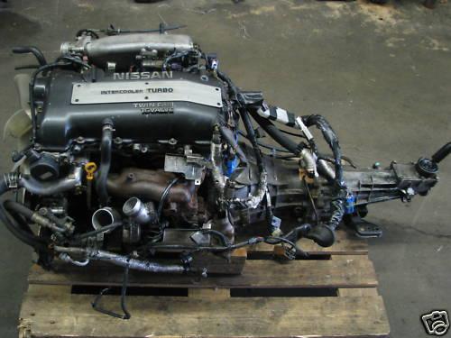
As can be seen, above, the colour of the rocker cover does not indicate which motor the car came from. Later model 180sx have a black top motor but it is not the ‘black top’ with the T28 turbo and VTC of the S14/15 models. The shape of the rocker cover is the reliable indicator, not the colour.
S14/15 SR20DET Advantages
There are two major advantages when using a later model SR20. The first is the turbo, which is the larger T28. This will produce more power at the wheels than a T25G with the identical supporting mods. The other is the VTC system, which changes the inlet cam timing to help spool the larger turbo quicker, and then changes back at the upper end of the rev range to optimise top end power. This system is covered in more detail below.
S14/15 SR20DET Disadvantages
In isolation, there are no real disadvantages. The only problems come when the motor is transplanted into the S13 chassis. The major hurdle is the different wiring loom and ECU. The best way to install the engine is with the S14/15 loom staying with the motor. Even so, it is not a straight swap as the S13 body loom doesn’t match. Some custom wiring is required. The S15 motor poses more problems. The 6 speed transmission may be an issue but the real concern is the speed sensor for the ECU being in the differential, requiring the diff to be changed as well for any chance of the instrument cluster working properly.
For this reason, the S14 motor is probably the pick, offering upgraded features with an easier install. There is some discussion of the S15 version having a slightly better turbo, but if you are going to upgrade it, the S14 version makes even more sense.
Pinpointing the Exact Model
By far the easiest way is looking at the code on the factory ECU, and then referencing the Nistune documentation. A simplified table is available on the following page:
http://www.plmsdevelopments.com/realtime.shtml
| Vehicle | ECU part number | NIStune board |
|---|---|---|
| S13 Silvia (SR20DE) | 52F00 (manual) | Type 3 |
| 52F10 (auto) | Type 3 | |
| S13 Silvia/180SX (SR20DET) | 50F00 (manual, “red top”) | Type 3 |
| 50F05 (manual, “black top”) | Type 3 | |
| 50F10 (auto, “red top”) | Type 3 | |
| 50F11 (auto, “red top”) | Type 3 | |
| 50F15 (auto, “black top”) | Type 3 | |
| S13 180SX Type X (SR20DET) | 60F07 (manual) | Type 4 |
| S14 Silvia (SR20DET) | 69F00 (manual) | Type 3 |
| 69F01 (manual) | Type 3 | |
| 74F00 (manual) | Type 3 | |
| 74F01 (manual) | Type 3 | |
| 75F00 (manual, EDM) | Type 3 | |
| S14a Silvia (SR20DET) | 80F00 (manual, JDM) | Type 4 |
| 80F10 (auto, JDM) | Type 4 | |
| 82F01 (manual, EDM) | Type 4 | |
| 82F04 (manual, EDM) | Type 4 | |
| 82F08 (manual, EDM) | Type 4 | |
| 83F00 (manual, ADM) | Type 4 | |
| S15 Silvia (SR20DET) | 91F05 (manual, JDM) | Type 4 |
| 91F07 (manual, JDM) | Type 4 | |
| 93F00 (manual, ADM) | Type 4 | |
| 93F10 (auto, ADM) | Type 4 | |
| RNN14 Pulsar GTiR (SR20DET) | 54C00 (early, JDM) | Type 3 |
| 54C60 (late, JDM) | Type 3 | |
| 69C05 (EDM) | Type 3 | |
| U13 Bluebird (SR20DET) | 1E000 (manual, JDM) | Type 3 |
| 4E610 (auto, JDM) | Type 3 | |
| W10 Avenir (SR20DET) | 95N11 (auto, JDM) | Type 3 |
| 95N15 (auto, JDM) | Type 3 | |
| N14 Pulsar (SR20DE) | 68C00 (manual, ADM) | Type 3 |
| N15 Pulsar (SR20DE) | 1N960 (manual, ADM) | Type 3 |
| N14 Sunny (SR18DE) | 58Y01 (manual, EDM) | Type 3 |
| B13 Sunny/Sentra (SR20DE) | 64Y00 (manual, 1993) | Type 3 |
| 64Y01 (manual, 1993) | Type 3 | |
| 71Y05 (GTi, manual, EDM) | Type 3 | |
| P10 Primera (SR20DE) | 62J00 (manual, 1991, EDM) | Type 3 |
| 70J15 (auto, 1993, EDM) | Type 3 | |
| 83J10 (auto, 1994, EDM) | Type 3 | |
| S13 Silvia/180SX (CA18DET) | 36F00 (manual, JDM) | Type 1 |
| 36F05 (manual, JDM) | Type 1 | |
| 36F11 (auto, JDM) | Type 1 | |
| 36F15 (auto, JDM) | Type 1 | |
| 39F00 (manual, EDM) | Type 1 | |
| 39F05 (manual, EDM) | Type 1 | |
| 44F02 (manual, EDM) | Type 1 | |
| 44F06 (manual, EDM) | Type 1 | |
| 44F07 (manual, EDM) | Type 1 |
My car was advertised as having an S15 motor, but the ECU code of 74F01 informed me it was from a manual S14 zenki.
Variable Timing Control
The VTC system makes the S14/15 motor much more drivable. Imagine an S13 motor with an adjustable inlet cam sprocket. It could be advanced to give the motor more low down torque, but would run out of breathe at high rpm. Alternatively, it could be retarded to give better power at high rpm, at the expense of low/mid end response. The VTC system achieves the best of these scenarios by altering the timing of the inlet cam.
From between 1050 and 5700 rpm, a solenoid is triggered by the ECU which allows the flow of oil into a mechanism at the front of the inlet cam, advancing the timing by 20 degrees. At idle and above 5700 rpm, the oil gallery closes and the timing returns to normal. This provides a more stable idle and more high rpm power.
The diagrams below are taken from the service manual (available on the resources page), and show the changes in timing of the inlet cam. More importantly, it shows a comparison graph of the timing change permanently on and off. The ECU activates the VTC system to get the benefits of each; the highest part of both curves. In the real world, VTC will allow you to have slightly larger turbo and not have the lag that comes with it.
The VTC Rattle
A common problem on S14/15 motors is a VTC rattle. Most sources claim that the gears inside the mechanism wear and create free play. The result is the motor rattling loudly like a truck. Whilst not damaging to the engine, the sound is very embarrassing. The video below illustrates the problem well:
An exploded view of the offending mechanism can be seen below. It is taken from an excellent page that details repairing the VTC rattle.

If you require this fix, expect to pay around $500 for the VTC gear and $190 for a replacement solenoid. One such supplier I have found is TAARKS.
Wiring the S14 Loom to the S13 Chassis
Keeping the S14 loom means it can plug into all of the parts of the engine without alteration. This includes sensors, solenoids, injectors, ignition system, etc. In the passenger footwell, it plugs into the matching S14 ECU. The trouble is the F4 plug, which expects to plug into a matching S14 M60 body plug to get power and interface with things like the fuel pump. The M60 body plug does not exist in the S13 chassis.
The following image is from the FSM and shows the engine loom, going through to the connectors in the passenger footwell. The F4 plug is labelled (G3 coordinates).

The pins for the F1 (ECU) and F4 plugs:

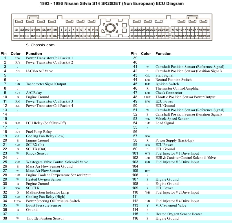
A pinout of the S14 zenki ECU:
Some pins from the F4 S14 plug need to be wired the S13 body for the car to run. The following is taken from a forum and has not been tested by myself. Follow it at your own consequences!
Here is what you need to make it run:
Ignition PWR S14(F4 Plug) Pin 40 B/R -> S13(F8 Plug) B/R
Main PWR to ECM S14(F4 Plug) Pin 48 BR?->S13(F8 Plug) B/R
Fuel Pump S14(F4 Plug) Pin 22 B/Y->S13(F9 Plug) B/P
Start Signal S14(F4 Plug) Pin 30 Or/L->S13(M53 Plug) Or
Injector Power S14(F4 Plug) Pin 40 R/L->S13(F8 Plug) B/R
O2 Sensor Power S14(F4 Plug) Pin 29 Br->S13 Any Switched Power
Speed sensor signal S14(F4 Plug) Pin 5 Y/G->S13(M53 Plug) Y/G
Fixing My VTC
Ultimately my issue was that an ignition switched 12V was not being provided to pin 29 in the F4 loom. The diagram below shows the wiring for the VTC:

In simple words, 12V is given to pin 29 from the F4 plug, travels through the firewall and to the VTC plug on the front left corner of the motor as a brown wire. The other pin of the plug travels back through the engine bay and firewall to the ECU to pin 113 as a yellow wire. When the ECU wants to activate the VTC, it grounds pin 113, allowing 12V to travel through the solenoid and open the gallery to the inlet cam gears.
Some tips when diagnosing:
- Applying 12V directly to the solenoid in the head of the engine should make it click loudly. When the power is removed, it will again click back into its starting position. This can be done with the engine off, and polarity isn’t important when applying 12V. If done with the engine running, the click will be audible but not as noticeable due to competing engine noise.
- A multimeter should measure 12V between pin 2 of the VTC plug (yellow wire) and ground, anytime the ignition is switched on, regardless of whether the engine is running or its rpm.
- A multimeter should measure continuity between pin 1 of the VTC plug (brown wire) and pin 113 of the ECU harness. The ECU harness needs to be disconnected so therefore the engine will be off.
- S14s have a neutral switch which prevents the VTC from activating when not in gear. If testing in an S14, have someone sit in the car with the clutch in and any gear selected. Revving the engine above 1050 rpm like this should make the audible click described in step 1 when listening in the engine bay. In an S13, the neutral switch won’t be connected, so you can do this test by yourself from the engine bay, revving the engine by hand with the throttle body.
My car passed steps 1 and 3, but not 2 and 4. This told me that the solenoid was physically working and able, and the correct ECU pin was connected to the plug. I therefore traced the issue to the F4 plug not receiving 12V on pin 29. Connecting this from the stereo wiring gave me success on all four steps, and I presume working VTC.
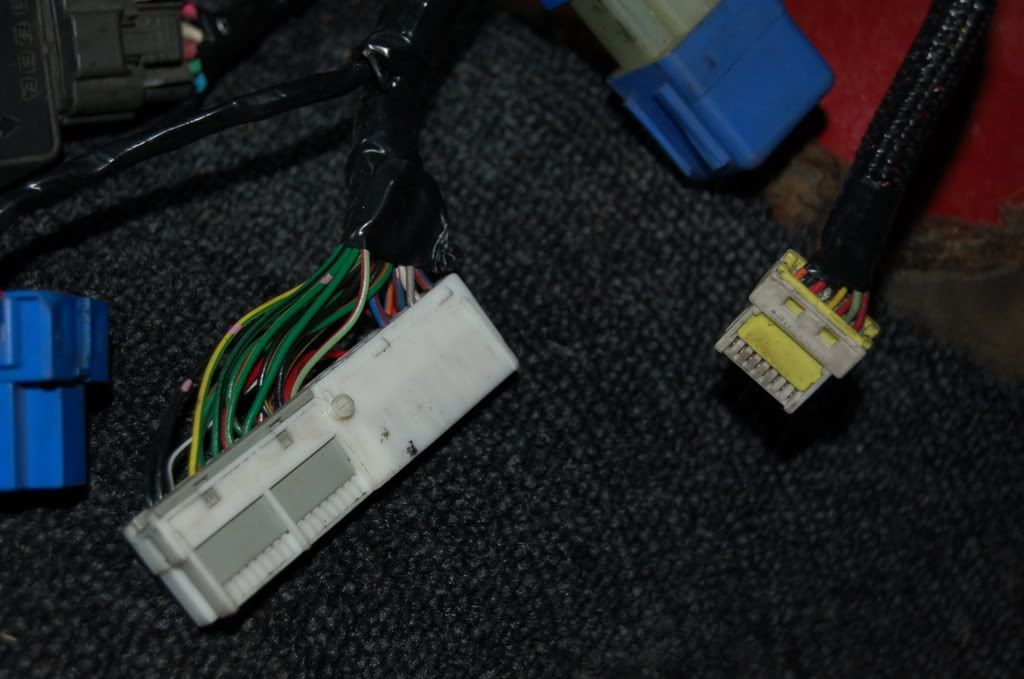
I was greeted by a mess of wires. The F4 plug was jammed up above the ECU. I identified it by matching it to the diagram from the service manual.

The F4 plug (not my car):

