This page deals specifically with the fitment of what is described as a ‘bolt on’ turbocharger. Consider it a step by step example, using the fitment of a HKS GT2510 to my own 180sx.
Alterations Still Needed
Although ‘bolt on’ is the basic principle quite often subtle changes are needed to have everything working 100%. For example, when recently trying to fit the Apexi AX53B60 to my car it was discovered that the turbine housings were different enough to stop the dump pipe from fitting. The wastegate splitter for the factory Garrett T25G was simply not needed as the Apexi unit had this section split with the design of the casting. The dump pipe splitter had to be cut off, despite having the exact same pattern flange.
Another common story is that the fitment of an S15 T28 to an earlier S13 model SR20DET requires rotation of the housing.
Oil and Water Lines
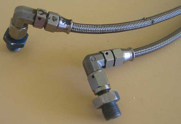
Quite often the factory metal water and oil lines require a little bending to match up to the new turbo. This can compromise the durability of the lines, with them prone to cracking. The best solution, if you can afford it, is to fit aftermarket braided lines. Not only will this mean a more reliable connection, but the ease of attaching the lines to the turbo and block is much greater without the load on the fittings.
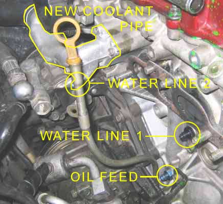
Below are the end fittings for the water lines that screw into the block. Please note that one of the water lines differs on S13 to S14/15 models. On S13s it connects to a rubber hose with a clamp which leads behind the cam cover near the heater hoses to the somewhere near the plenum. On S14/15s a banjo fitting attaches to the cast metal coolant pipe that runs under the crank angle sensor to the top right hand side of the radiator. Keep this in mind when buying a kit specifically for one model or the other, as you will need to make changes for everything to bolt up.
For s13s I would recommend finding an S14/15 coolant elbow and retaining the lines for this, the setup seems much easier to access and work on.
New braided lines can be purchased from companies such as Horsepowerinabox here. Motorsport Connections in Seven Hills is also highly recommended. GKTech offers ready made S13 and S14/15 braided lines on their website too.
Oil Restrictors
Recent research has lead me to believe that an oil restrictor is required for most ball bearing turbos. Where as a plain bearing turbo requires a thin pressurised film of oil between the bearing surfaces to function, a ball bearing turbo only needs a small amount of oil to lubricate the bearing. The difference can be compared to that of a bearing in an engine, and the meshing of gears in a gear box. Like a plain bearing, the bearings around the crank in an engine require an oil film to stop the two surfaces machining each other out, but the transmission gears only need a bit of oil to keep everything fresh. Obviously it still requires lubrication but the consequences would slower impacting compared to a lack of oil in an engine.
Now imagine that the gearbox has too much oil. Imagine that the entire casing is filled with oil so that everything is submerged. It’s easy to see that the gears will encounter a lot more friction from the surrounding environment, and will become harder to accelerate. The same applies for the ball bearing turbo. Too much oil supply leaves a possibility of reducing the responsiveness of the turbo.
It Is necessary then to limit the supply of oil to the turbo using a restrictor. This needs to simply be a section in the oil feed line that has a much smaller diameter. Apparently HKS recommend a 0.6/0.7mm restrictor for their turbochargers, which might add performance but clearly will have disastrous results in the engine is not maintained. The smaller the orifice the easier it would be to get it clogged from bad oil particles. It is even more essential then that very regular maintenance is performed. A complete blockage of oil supply would destroy the turbo fairly quickly you would think.
I have made my own restrictor my modifying the fitting that screws into the top of the turbo. It is simply a matter of welding up the centre hole and then drilling it the required diameter. Take extreme care that the profile of the mating surfaces is kept true or the connection won’t remain water tight. Also take care to ensure there are no rough welding dags on the fitting. Such features attract bad oil particles forming.
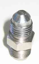
Seen below (left) is the fitting freshly welded up by the local welding workshop for $10. After welding it he used a grinder to match the correct shape so that the fitting will still connect securely with the braided line. Note that the original diameter was about 4mm (the width of the top face).
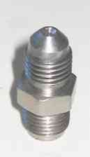
The next step is drill out the welded section from the rear. After this a quick counter sink drill with an original diameter (4mm) bit will clean up the inside surface. As seen above (right) I chose a 1mm diameter oil allowance. The oil restrictor is now finished and the turbo ready to go on.
I have been told that GCG Turbos sell oil restrictors so some may wish to pursue that path.
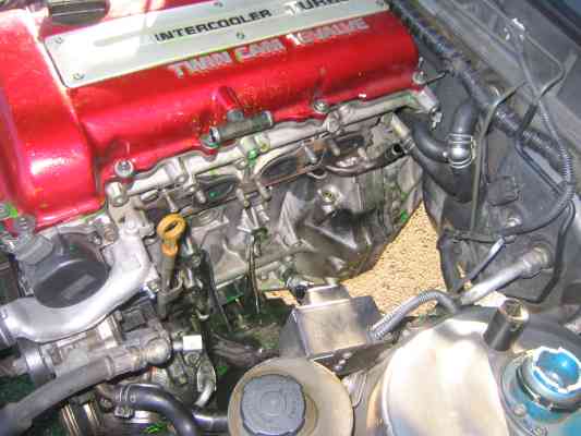
Removing the Stocker
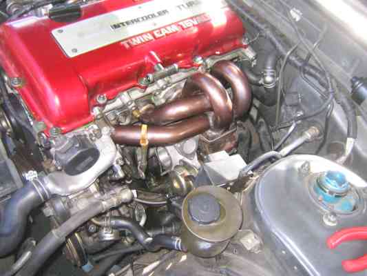
This will be similar to the info found in the manifold page, except using greater detail. Your engine bay at the beginning will look something like this:
A great tip if the day is good is to unbolt the bonnet before starting. The extra light is reason enough but your back will thank you for the extra head room, preventing as much bending over. Strut braces should come off immediately.
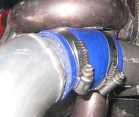
The first step is to remove the intercooler piping from the turbo compressor outlet to the most convenient join, as well as the induction pipe leading from the compressor inlet snout to the afm and air filter. I managed to remove all of mine as a single unit, as the BOV now joins the two with its venting pipe. The snout that bolt onto the compressor housing should now be removed. Next remove smaller things the oil breather hoses running along the top of the cam cover.
With all of the superficial things out of the way you can begin to loosen the actual head to manifold bolts. A combination of 14mm spanners and sockets will get each one undone from the top. There should be no need to work from underneath the car at this stage. You won’t need to until you unbolt either the dump pipe from the back of the turbo, or the dump pipe from the front of the cat.
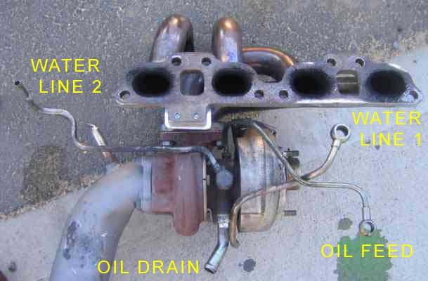
Oil and Water Lines
The next step is trickiest. It begins by draining the coolant from the radiator. The best place to do this is the large hose at the lower left hand side of the radiator, just underneath the front bar lip. Once undone unscrew the radiator cap to allow the coolant to drain fully. After a few minutes wait you can now undo the water lines. The first has a 19mm head and goes into the block. Simply unscrew and be ready not only for more coolant to go everywhere but also to catch the little copper washers either side of the banjo. These are invaluable.
The next more difficult coolant line (on an S13) goes up near the heater hoses and around the back of the rocker cover. It is a metal pipe running into a rubber hose, fixed with a small hose clamp. This can be very hard to get to, and if not touched previously a small bracket securing the metal pipe will get in the way. If you are planning to ever do this again ditch it (unless you like a challenge).
S14/15 owners simply have to undo another 19mm banjo bolt that goes into the coolant pipe underneath the Crank Angle Sensor.
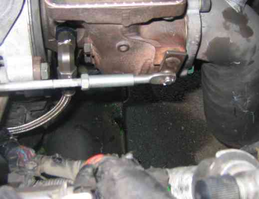
Now the oil feed line can be undone from the block. It has a 17mm banjo bolt and is located down near where the dipstick joins to the block. The washers here are extremely easy to drop down into the abyss so it is recommended a white rag be placed underneath the area to catch them. In my experience I found that only a drop or so of oil will be lost when this fitting is undone. It is still recommended but not completely necessary then to drain the oil prior to removing this fitting. Fresh oil on a new turbo is always a good idea.
The last item remaining is the oil drain going into the sump. This is a metal pipe strapped to the turbo, going into a hose clamp secured rubber hose. Fairly straight forward here, as it can be done from above but some may find it easier to do from underneath.
The following picture is provided for reference is locating each line in question:
Removal
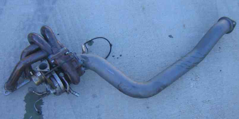
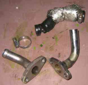
Now the turbo/manifold/(dump pipe) assembly can be pulled out of the engine bay. It will leave a large cavity behind it:
The turbo/lines/manifold/dump pipe assembly:
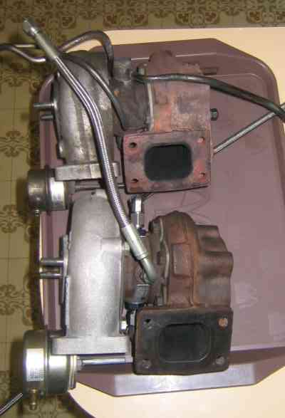
Garrett T25G vs HKS GT2510
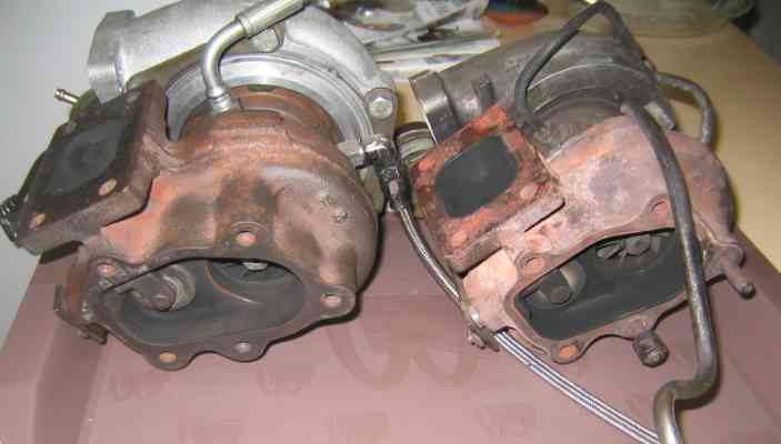
As can be seen in the series of images below the two turbos have very similar dimensions. All four flanges over the compressor and exhaust housing match perfectly, meaning the that intake snorkels, manifold and dump pipe will also bolt on.
The compressor cover of the HKS turbo is much larger. Note also the diameter of the wheel inside the housing. Although they have the same internal inlet snout diameter, the HKS matches this with wheel width where as the Garret has a stepped section in the housing to accommodate a smaller wheel.
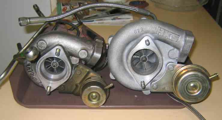
Overall lengths are very similar:
The exhaust sides are very similar. The housing on the HKS (left) is slightly larger overall. The wheel diameter and wastegate diameters appear near identical.
It is interesting to note that the locations of the oil and water lines are the same. The oil feed enters on the top of the core with the drain underneath, and the water lines enter and exit on opposite sides like factory.
By the way as illustrated McDonald’s trays make superb surfaces to put this type of thing on.
Preparing for Braided Lines
Since those horrible factory metal lines are being replaced, the initial steps of fitting the braided lines can be made. If you are upgrading to an S14/15 coolant elbow pipe then now is the time to swap it over. The braided line fittings can now be screwed into the block and coolant elbow, as shown in the image below. Remember to use copper or alloy washers in these connections.
If upgrading to a later model coolant elbow then you must plug up the old coolant line to prevent a large mess. I used a nicely sized bolt, and then clamped the original hose clamp tightly over the top. Hopefully the rubber hose will be forced into the thread of the bolt and form a nice water tight connection.
Reassembly
The first steps taken should be to bolt on the braided lines at the turbo end, making sure each section is tight. There will not be much room to do this later. Next bolt the turbo to the manifold. A new gasket and new studs and nuts are highly recommended here to ensure long term integrity. If the dump pipe was removed with the assembly then bolt it back on now, again using a new gasket if required.
Carefully lower the assembly into the engine bay, and loosely slide the manifold over the head to manifold studs. As you would have noticed when removing them, some of the nuts securing the manifold to head need to be put in position before the manifold is completely in place due to runner to head clearance issues. Check each one to ensure none are missed. At this stage do not do them up tight, leave some play in the entire assembly.
This will assist when securing the braided lines to the fittings waiting in the block. Do up all of the braided line fittings at proper tightness before then tightening the head to manifold nuts. My lines were not quite right in their shape and length, since they had come off a different turbo setup using different line placement. This made things a bit harder, with highlights being not able to use the original oil line I had intended, but having to swap it with one of the water lines. Another fitting I cross threaded when screwing on tight, and had to reshape the thread using a file and blade. After an hour or so it went back together well. Immediately fill up the engine coolant and oil before you forget.
Here we have the manifold secured, along with all of the fittings:
If you are like me you will discover that there is some difference in oil drain pipes from turbo to turbo. The centre diameter matches but the two holes used to bolt the pipe onto the base of the turbo were placed wider on the original pipe. It would not fit the hks turbo. I ended up using the left over oil drain pipe I had from the Apexi turbo, which had the correct spacing between holes. The holes however had an incorrect diameter, being too small. I used an 8.5mm drill bit to drill out the holes larger, and also elongated them a tad to assist in alignment. After this the flange and pipe bolted up fine.
Now is a good time to test the oil flow through the turbo. Leave the oil drain undone and hanging over a bucket, and disconnect the CAS to prevent the engine from firing. Now crank the motor until a thin stream of oil is coming from the oil drain. This took quite a few cranks for me, but in the end plenty of oil came out onto the ground. Those doubting the effectiveness of a 1mm oil feed should see the image below. The turbo is now lubricated for first startup. Connect the oil drain rubber hose which in my case was a fresh piece as I ruptured the old one taking it off.
The oil through the turbo, the black puddle on the ground is all oil:
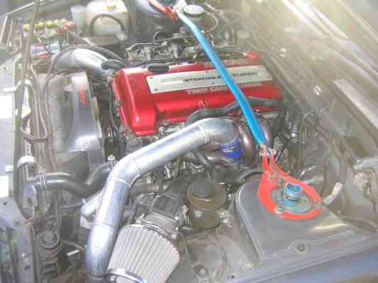
It is simply a case of putting on what has been removed with the dump pipe, intercooler piping, oil breather hoses, induction pipe, afm and air filter. Double check that no tools are lying around in the engine bay, and that all parts are back on.
First Start
Hopefully everything starts up without any leaks and the car is ready for some precautionary trips around the block. Take care to watch your boost gauge when you spool the turbo for the first times. The last thing you want is to realise the wastegate lines are undone or the wastegate jammed and to lose the motor from massive overboost.
The only leak I encountered was from the old water feed I had plugged up. A slow drip indicates I need to redo it with a larger bolt or tighter.
There was a a bit of smoke and a burning smell also coming from the assembly. This is common after such a process and is the oil and grease from your hands burning off as the manifold heats up.
Compressor Outlet Snorkel Problems
Besides the oil drain pipe the only thing that didn’t want to fit back was the 3 bolt flange compressor outlet snorkel. The flanges matched well but the snorkel fouled on the manifold runner. The neck where the intercooler hose joins also fouled on another runner. My temporary solution was to grind away from the body of the part to clear the first runner problem, which worked but unfortunately I went a tad too far in one area and left a small hole. It is safe to assume that a slight leak will be coming from this area. For the neck problem I ground a bit of the lip away, and also elongated the 3 mounting holes so that the snorkel could be rotated slightly away from the runners. A few bits of spare hose clamp are wedged in between the silicone hose and the manifold runner to prevent the hose melting. This seems to working well for now.
The alignment between the snorkel and the intercooler piping is very poor, mostly due to the dodgy work done by Hills Motorsport in the first place. The was always shonky, but now the problem is worse thanks to the new snorkel position. I will have to get the snorkel modified by a workshop and probably the end of the intercooler piping too before the connection is 100%.
I very much feel this clearance issue wouldn’t have happened with a factory manifold. The problem is down to the manifold not the HKS turbo.
Driving Impressions
With the Blitz ebc switched to ‘off’ (meaning no added boost or wastegate creep assistance), the 2510 makes ~9psi on wastegate pressure. The t25g used to make around 6-7psi in the same way. Response so far is slightly down as is power, but not by a great deal. Power feels down by maybe 25 rwkw, but response is still much closer to stock. This is perfectly normal though from switching to a slightly larger turbo running 5 psi less boost. The turbo really won’t come alive power wise until some decent boost is wound in. Response will improve dramatically once the ebc is allowed to target wastegate creep with a more aggressive setting. I’m predicting response to be at least as good as factory once it’s tuned.
Unfortunately after a few boosts I could hear a slight leak coming from the turbo area, implying the dodgy compressor snorkel is playing up. Response was down as was power. Nothing to do but to get the piping fixed up.
One cool thing is the way the turbo continues to spin for around 20 seconds after the engine is switched off. This is the same as the HKS GT2540 that came on the car but went back to the previous owner.
Where to now?
The turbo can’t be boosted until I have the fuel system to match, which can’t be put on until I have the ecu retuned. So the car must remain driven like this until tuning, when everything goes on including the z32 afm and I expect to drive out of Unigroup with at least 210rwkw.
