*When originally written, this page dealt with the installation of a Blitz SBC iD II electronic boost controller. The principles and guides on this page should translate over to many other controllers, as they function in the same way.*
The Blitz SBC iD II at the current time of writing is the flagship of the Blitz boost controller range. It uses the same twin sequential solenoid design of the cheaper Dual SBC type R and the SBC DC, but with a full function LCD screen. Please note, the only difference between the iD II and the iD it replaced is that the screen on the iD II is green whereas the previous model was blue. I had previously planned to build a very nice manual bleed valve design as seen on Autospeed, but was unable to purchase the components off the pneumatic supplier’s website. My mind then turned to the cheapest japanese electronic boost controllers, such as the Greddy Profec B spec. This ebc is fantastically simple and for the money you can’t go wrong, therefore I wished to purchase one. But delays each week meant my money slowly accumulated over a month and a half, until I could just scrape for a new SBC iD II.

Features
- Full automatic boost control (put in amount and it does the rest)
- Gain control (boosting speed)
- Scramble boost
- 4 channels or boost settings
- Multi-unit (psi, BAR, kg/cm2, kpa)
- Record and playback
- Bar graph display with peak hold or
- Line graph display of boost vs time
- Overboost warning, buzzer and limiter
- Actuator integral wastegate or external wastegate function
- Controls up to 2.5 BAR approx.
*additional features when optional data harness is used*
- Three inputs for data
- Data can be from any linear voltage signal in the car, the limits are put in and a unit given and the voltage will be displayed)
- eg 1. Throttle Position Sensor used as input. 0v as min, 5v as max, % as scale. Will now show throttle position.
- eg 2. Air Flow Meter used as input. 0v as min, 5 volts as max, % as scale. Will now show afm output voltage.
- Any data can be seen in digital bar graph mode or time vs data line graph mode. Record and playback can also be used.
*collective features when combined with the symmetrical Power Meter II*
- Boost vs Speed mapping
- Speed Display
- Performance testing (0-100kmh, 0-400m, etc)
- On board chassis dyno (based on acceleration when vehicle weight in input)Information LinksBlitz Australia website information:SBC iD IISBC iD
Instruction Manuals:
Installation
Installation is very straight forward, with a no hassle install taking approximately half an hour. The Blitz SBC iD II comes with every little part needed to install the product in a professional way. I had never had a brand new japanese product before, and boy was I impressed. Only problem was the installation instructions are all in Japanese. Luckily I already had a copy of the english instructions (link above).

Wastegate Hoses and Solenoid
The factory wastegate hoses on a SR20DET equipped car are teed off to go to the factory wastegate solenoid. This must be removed from the system for the ebc to work correctly, so after removing the factory wastegate hoses block this off immediately. Next run some of the new blue wastegate hose from the turbo outlet intercooler piping to the IN port on the solenoid unit. After this run some wastegate hose from the OUT port on the solenoid unit to the wastegate actuator. Make sure clamps are used at each connection to ensure the hoses do not come off. If they do the car will build as much boost as it possibly can, the wastegate will never open which is obviously very bad news.
The loom from the solenoid unit needs to run into the cabin to the control unit. I chose to run it through the small opening in the engine bay that leads to the inner guard area. Simply pierce a small hole in the rubber boot that seals the inner guard area and the cabin and run the loom through. In the cabin this will be right up behind the glovebox.
The control unit now only requires a 12v ACCESSORY or IGNITION ON power supply to be connected to the red wire in the loom, and a the black wire to be grounded. The final step after plugging in everything is a vacuum line going into the back of the control unit. Teflon hose is supplied which attaches to the metal Blitz Tee, just push it into the hole and it grips, even though it doesn’t look like a reliable joint. A good place to tee into would be a vacuum line already under dash for a boost gauge, which is where I did. Everything is wired and connected so now just pick a good place for the display unit.
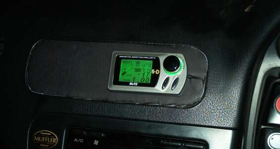
Shown here is my chosen location, which is in the place of the factory air vent centre dash. I really wanted it to be visible and useful so this seemed the best place. Shown is a temporary cardboard mount that will be replaced at a later date.
Initial Problems
The installation instructions attempt to make it very clear that it is important to keep all hoses as short as possible. However, the wording is not clear, stating:
“Keep the valve unit away from hot components but within three feet from the turbo.
CAUTION: more than three feet away from the turbo can cause bad response with boost surge and boost spike.”
You can tell that it is important to keep the solenoid close to the turbo but it is not so obvious that that is to keep the wastegate hoses short. My first installation of the solenoid was within three feet of the turbo easily, but the wastegate lines were quite long compared to the factory units. This gave the car shocking boosting response, with surging that made the car feel like it was bunny hopping.
Modification of all Lines
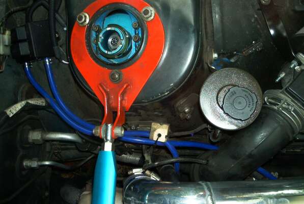
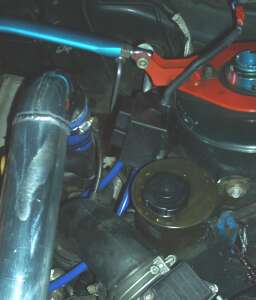
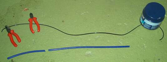
To combat this, I decided with help from members of NissanSilvia.com and Silvia NSW to attempt to shorten all lines as much as possible. This required movement of the solenoid unit to the strut tower above the wastegate. Also all excess vacuum line that I had failed to trim previously was removed, still teeing off the boost gauge line under dash.
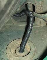
The image below left shows the new position of the solenoid, and the image below right shows the amount of vacuum line and wastegate hose removed from the installation.
 |
 |
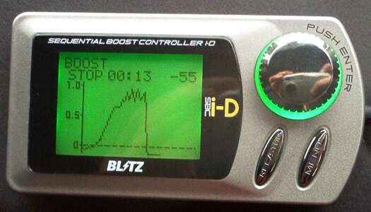
Immediately, the boosting response picked up and stabilised, but was still not perfect. I then moved the control unit to just near the driver side kick panel fuse box, so that vacuum line could be run directly to a tee off the intake manifold. This saved about half a metre of vacuum line and improved boosting characteristics slightly. Below left shows a quick boost in first gear then second, and below right shows a steady boost from low rpm in fourth gear. Not perfect but greatly improved over the initial install. Before the surge felt very violent, but now it is only noticeable by observing the screen.
 |
 |
Blitz SBC iD II General Boosting Characteristics
After playing with the boost controller for a week or so, I have noticed a few patterns in which the ebc works. After changing the level of boost or the gain setting, the ebc will slowly try and reach the best boost curve, improving each time. The first time you floor it after changing, it will feel extremely laggy, and probably only reach half of what you put in. The next time will be slightly improved, until you have boosted enough times for the controller to recognise the best way to control its solenoid. Therefore, fine tuning can not be undertaken very quickly, which can be a little bit frustrating. You must remember however that this is on purpose, so the the car does not overboost and cause any damage by jumping the gun excitedly. Appreciate it as the safety measure it is.
A very nice observation was how the drivability of the car has improved after letting the ebc learn a setting for a while. Boost comes on very early and strong, making the car even more tractable than before. The top end seems to be improved too, seeming more eager to rev out. Previously the power felt like it was dropping off after 5500 rpm, now it is strong to at least 6000 rpm, which is very nice. Hopefully the addition of a bigger catalytic converter will enhance this again slightly.
